Fountain Structure – By: Chris Roy, Director of Design – OTL
Posted in Insights -
Disclaimer: I am not a structural engineer, and this blog post is meant in no way to cover structural engineering for water features, which should always be done by a professional. The intent of this article is to give designers an overview of some of the specialty engineering that should and/or can be used in water feature design so they can address these issues with the structural engineer on the project and make sure that these details aren’t left out of scope.
“
The vast majority of architectural water features are built with a reinforced concrete structure. Just as with a building, proper testing and preparation of the subgrade is of key importance.
” Chris Roy, Director of Creative Design for OTL.
Water is heavy, and the grade or structure below the fountain must be engineered to support a load which is able to move, be drained away, and refilled time and again. Subgrade should be compacted per the geotechnical engineer’s direction depending on soils reports and may need additional preparation and/or remediation to ensure suitably for construction of a fountain above.
Show Fountain Designs
While fountain designs vary widely, when distilled down to their essence, some form of basin is nearly always a primary component. These water-containing vessels are most often coated with a waterproofing membrane, and as such the concrete work must be smooth and free of defects, with no traces of form release which would inhibit the adhesion of surface coatings. There are specific projects when a waterproofing admixture to the concrete will be specified; in these instances, the structural concrete is often serving as the final finish material, placing even more importance on surface quality.
While the waterproofing membrane is meant to seal the basin, it is really the concrete basin structure which should be thought of as the primary water-containing vessel. As such, detailing and materials selection for the fountain structure are of prime importance.
The concrete for water features should be 3000PSI minimum compressive strength at 28 days, though concrete of higher strength can be advantageous as it has lower porosity and is more watertight. In places with cold winters, using air-entrained concrete will help ensure the fountain is not prematurely damaged by freeze-thaw cycles.
Occasionally we see drawings showing a fountain basin constructed with CMU’s, which is never a good idea; a block wall is by definition full of joints, the rough texture is difficult to waterproof, and the material is very porous, so water that penetrates through voids in the waterproofing quickly wicks through the wall. Fountain basins should be concrete; CMU may be fine in some instances behind a waterwall, above pool level, with specific waterproofing protection precautions taken, but a concrete wall will always be the better option.
Construction Joints in Water-containing Basins
Construction joints in water-containing basins should be kept to a minimum and must be carefully detailed and constructed. A monolithically-poured basin is the best option when possible, but these are typically only feasible with smaller fountains.
A good bond between adjacent concrete is a necessity for submerged construction joints, and a key element in achieving this is constructing the joints with continuous linear keyways. Cured concrete along a joint should be coated with a bonding agent before placing new adjacent concrete. These joints should further be protected with the use of continuous waterstops to prevent water infiltration and protect steel reinforcing bars from the corrosive effects of fountain water. Best practices utilize stainless steel or epoxy-coated dowels across the joints instead of standard steel rebar.
Waterstops in Show Fountains
Waterstops should be placed within the wall on the “wet side” of the concrete, so that they prevent moisture from corroding the reinforcing bar. There are a variety of different waterstop types available for various applications. We prefer to use swelling-style waterstops, typically Cetseal RX101 or RX102 (depending on the thickness of the wall). These are manufactured from bentonite clay, and are adhered within a joint and expand to fill any void space when activated by water wicking into a joint. Keyway detailing and wall thickness are particularly important with the swelling waterstops to ensure that the waterstop material is properly encapsulated and the concretion section adequately reinforced, as the swelling action can be quite strong and is prone to crack or blow out an improperly detailed joint. Ribbed PVC waterstops are another option though can be difficult to install in the field, particularly with tighter radii curved walls often seen in fountain construction. With PVC waterstops, extreme care must be taken to ensure that all joints are properly welded, and that they are not tied back to the rebar in such a way that they prevent complete encasement of the rebar and waterstop when concrete is placed.
There are projects which, due to their size and/or specific site conditions, require more complicated joints in the concrete, such as stress-relief joints and expansion joints (both partial-movement and full-movement). When such joints are unavoidable, there are several methods and associated products available to address sealing the joint while allowing for movement.
Stress Relief Joints
Stress relief joints (also commonly called control joints) are the most basic of these specialty joints and are introduced in large slabs where cracking of the slab is likely to occur due to shrinkage of the concrete during curing, and/or due to geometry of the form being poured, such as inside 90° corners. These are not joints per se, as they occur along the surface of a monolithically poured slab; they are intended to introduce a defined weak point in the slab to control where future potential cracking will occur. In normal slab construction, this is largely done for aesthetic reasons, whereas the crack will be hidden in the shadow line created by the joint; in a water feature, their importance is functional; the intent of stress relief joints is still to control potential cracking, however they also give the fountain builder an opportunity to preemptively seal the joint, so that a future crack within the joint does not cause a leak that has to be repaired. The bottom surface of the joint should be isolated with a polyethylene bond breaker (flat tape or backer rod, depending on the profile of the joint), and filled with a suitable submersible caulking such as polysulfide sealant, which bonds to both edges. If a future crack does develop within the joint, it will not affect the caulking, and the basin will not leak.
Movement Joints
Movement joints, generally speaking, require the use of specialty waterstops, stainless steel dowels, and proper installation of a suitable caulking material with bond breaker to allow for stretch without rupture. Partial-movement joints typically allow movement in one lateral direction, and the joint is reinforced by stainless steel dowels which are installed with bond-breaking plastic sleeves on one side; these joints are typically sealed with an accordion-style bottom-seal waterstop at the underside of the slab, as well as polysulfide sealant on backer rod at the top of the slab. Full movement joints do not typically have any crossing reinforcing bars and should only be used when absolutely required by the structural engineer (such as a fountain basin partial on structure and partially on grade). These are typically sealed with a center-bulb waterstop which allows for shear movement in multiple directions, along with backer rod and polysulfide sealant at the top of slab.
Concrete Basin Walls
When concrete basin walls are constructed with standardized formwork, extra care must be taken in the installation of use of the formwork itself. It is very typical construction for a concrete wall to be built on top of a concrete floor; typical contractor practice is to install kickers and cleats to reinforce the walers and strong backs, nailing the cleats into the floor slab. This should be avoided in fountain basin construction, as the nails create holes which are weak points in the floor slab and could lead to future cracking and/or leaks. If required, the cleats should be anchored with weights or horizontal reinforcements wedged into position. OTL’s standard construction practices include hanging interior forms so that basins can be poured monolithically without the need for cleats. This not only saves time, but ultimately results in a better end product.
Snap ties are another issue with standardized formwork, as they can introduce yet another opportunity for leaking or corrosion. Removable snap ties with a plastic sheath should be avoided, as the plastic sheath remains in the wall and is very hard to seal. Breakable snap ties should be stainless steel to avoid rusting, which could lead to expansion and spalling of the concrete or staining of light-colored finishes. All snap tie holes should be filled with a suitable polymer-modified grout, or a preformed concrete plug epoxied into the conical hole when applicable.
Wall thickness is determined by a number of factors, both aesthetic and structural. A “typical” fountain wall is 8” thick, which allows 3” of concrete coverage over each side of a central mat #4 of rebar 12” on center each way. A “typical” fountain floor slab is often 6” thick, with 3” of concrete coverage at top and the rebar placed closer to the subgrade side of the slab, also usually #4 bars 12” on center each way. Depending on the design of the fountain and local site conditions, it is common for structural engineers to specify thicker walls, double rebar mats, depressed footers, etc., all standard items in concrete engineering.
One of the fountain-specific details we see often are allowances required for mechanical items such as skimmers; a typical front-access skimmer needs a 10” minimum wall thickness to ensure adequate concrete coverage over the back of the skimmer. Depending on the aesthetics of the fountain and the location of the skimmer(s), this may necessitate using a 10” basin wall overall or increasing the thickness of the wall with a gradual buildout on either side of the skimmer. The latter detail can easily be hidden on a round fountain with a wide coping and non-patterned exterior walls; the thicker over-all wall is most likely the best solution with rectangular basins or the fountain is to be finished with a modular cladding system. When pilasters, planters, and seatwalls are introduced into the design, these architectural elements can often serve double-duty as the location for skimmers and other in-wall equipment, so that the increase in wall thickness can readily be hidden.
Thinner walls present a challenge all their own and are typically requested for aesthetic reasons. 6” thick concrete walls are generally about the minimum, though there are special solutions for special situations, such as certain non-corrosive reinforcing methods, glass-fiber reinforcement and more. These must be looked at on a case-by-case basis.
Reinforcing Materials for Specialty Projects
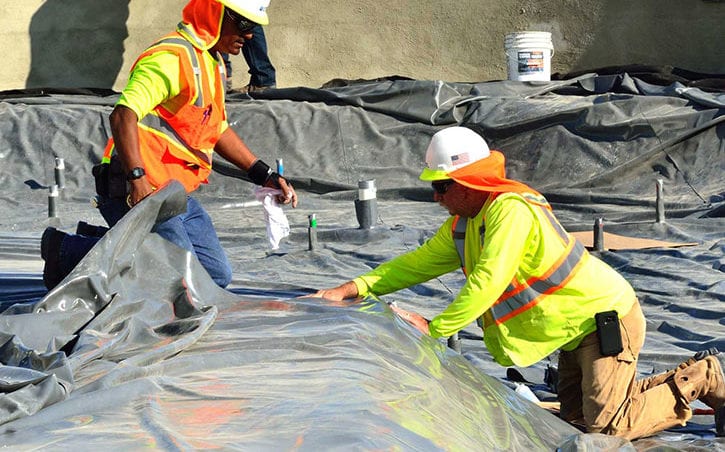
In addition to a variety of reinforcing materials at our disposal for specialty projects, OTL is also very well versed in a variety of construction techniques which differ greatly from standard “slab-on-grade” construction, and really allow us to put more budget into creating amazing water displays instead of spending it on time and materials below grade, where they’ll never be seen or appreciated. While most people think of fountains as being built like a pool or basement – concrete floor, concrete walls – many of our most well-known fountains forego the traditional reinforced concrete floor. Our preferred approach, when possible, is to build the basin perimeter with cast-in-place concrete walls, waterproof the walls, then attach a rubber pond liner around the perimeter using stainless steel batten strips. Our crews then pour a 4” thick protective layer of concrete over the liner, lightly reinforced with galvanized wire mesh, and form the fountain floor and special geometry such as jet troughs or other equipment depressions. All plumbing and electrical penetrations are sealed with rubber boots where they penetrate the liner, instead of more expensive stainless steel and/or brass waterstop penetrations used in a typical slab. The thinner slab and reduction in reinforcing materials offers a notable cost savings for our clients, and the construction methodology has proven to be very effective.
Clearly there are many specialty details that go into structural design for water features, and the technology of the field is always improving. New materials like basalt rebar, better sealants, and waterproofing admixtures with a variety of properties allow us to create forms that weren’t feasible a few decades ago. Taking a step back and looking at the purpose of the fountain’s structure from different perspectives is important too, and really gives us the ability to ensure that we’re able to build as efficiently as possible and utilize our client’s budgets where they’ll best be appreciated – in amazing water displays.

Chris Roy is the Director of Creative Design for Outside the Lines, Inc. In this role, he leads the company’s design efforts, working with developers, architects, and landscape architects, as well as engineers and vendors. Contact him at ChrisR@otl-inc.com.